red-y smart pressure controller

Digital Pressure Controllers for Gases with integrated Flow Measurement

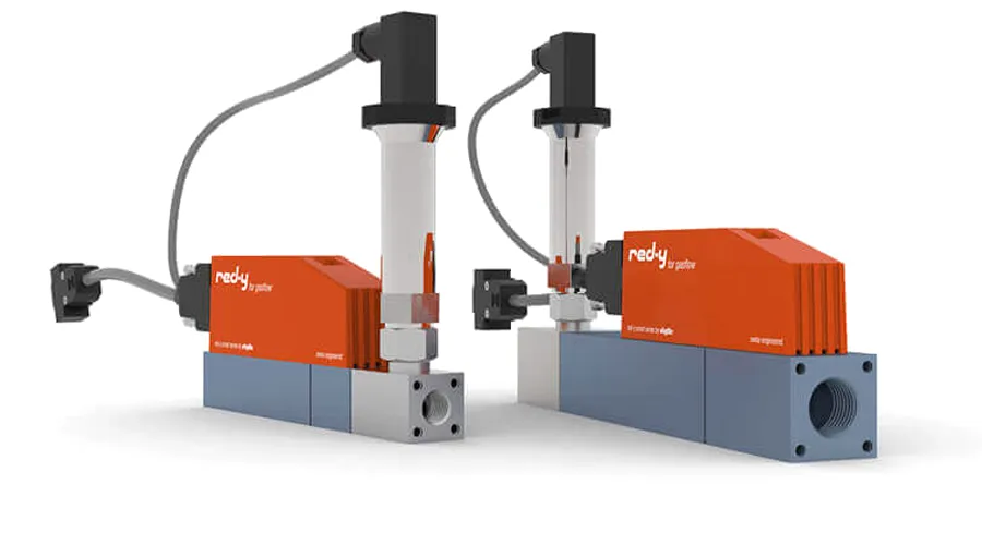
The electronic red-y smart pressure controller combine the reliable technology of our digital mass flow controllers with electronic pressure control. The devices automatically control a predefined process pressure and at the same time measure and/or limit the flow rate. On-the-fly switching between pressure control and flow control offers maximum flexibility.

Key Features

red-y pressure controller – Elektronische Druckregler für Gase mit integrierter Durchflussmessung

1 Device – 3 Functions

The pressure controller combines three functions:

  • Pressure controller
  • Pressure controller with flow measurement/limitation
  • Flow controller with pressure measurement

The following instrument versions are available:

  • Integrated pressure control
    Accuracy:± 0.5 % of full scale
  • Integrated back pressure control
    Accuracy:± 0.5 % of full scale
  • Pressure control with external pressure transmitters
  • Pressure controller with gas mixer function

Analog & Digital: 2 in 1

The pressure controllers make use of the latest CMOS technology and have a digital (Modbus RTU) and analog interface as standard.Profibus, Profinet RT and EtherCAT interfaces are available.

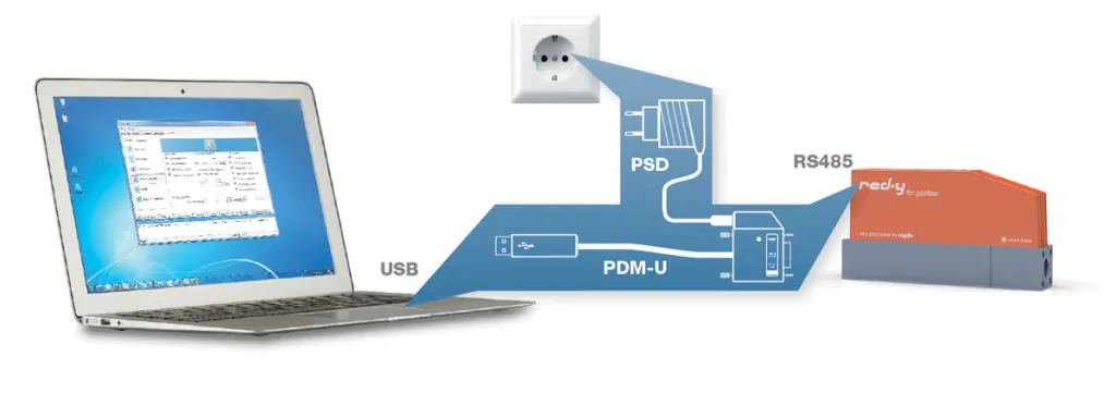
wide range of cables and power supply units for fast integration of the red-y smart pressure controllers is available:

Analoge & digitale Schnittstellen: Modbus, Profibus, Profinet RT und EtherCAT

Software get red-y

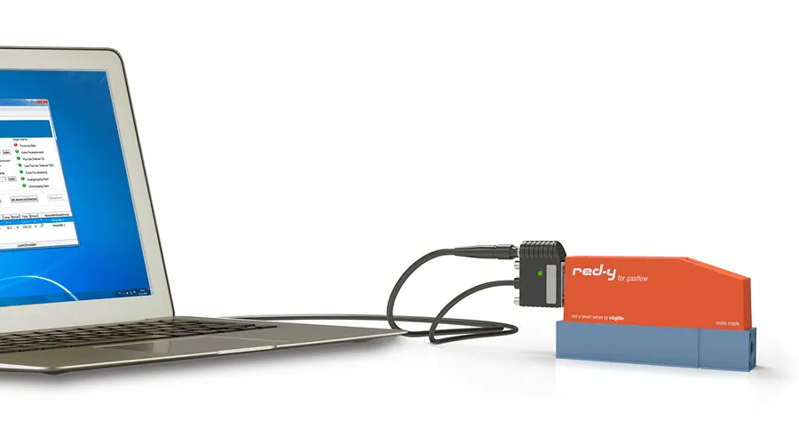
Efficient device management with the free get red-y software:

  • View flow rate & temperature
  • Change set points
  • Select measured gas
  • Visualization of measured data
  • Adjusting control parameter

Optional modules get red-y software:

  • Datalogging
  • Gasmixing

See all available cables and power supply accessories for easy PC connection.

Options

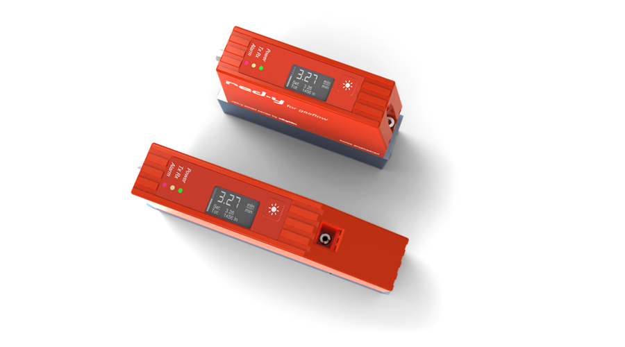
Built-in display
Display includes: Flow rate, totalizer, unit of measure & set point control

Multigas
One controller or controller can be used for up to 10 different gases or gas mixtures

Profibus
The instruments are available with Profibus interface: DP-V0 & DP-V1 protocols

Industrial Ethernet
Two industrial ethernet protocols Profinet RT and EtherCAT are available

IP67/ATEX Versions
red-y industrial pressure controllers are available as IP67/ATEX versions

Mass flow meters and mass flow controllers with local display
Massedurchflussmesser und Massedurchflussregler mit lokaler Anzeige
It‘s a red-y smart

The pressure controllers combine the innovative equipment design of the red-y smart series with the development competence of Vögtlin Instruments GmbH. High-quality components ensure long and trouble-free operation.

Operating Status Indication

The instruments offer a built-in LED status indication

3-Year Warranty

High-quality components ensure long and trouble-free operation (does not apply to calibration, options and accessories)

Versions

red-y pressure controller - electronic pressure regulators for gases with integrated flow measurement

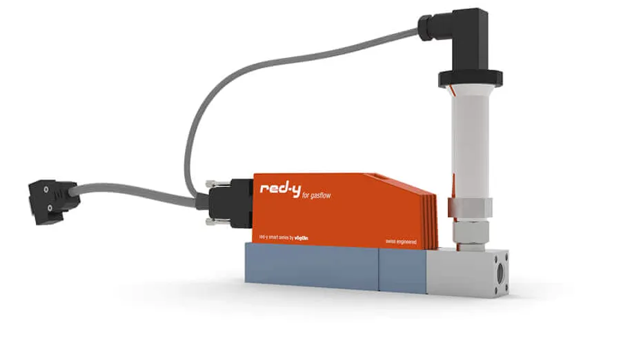
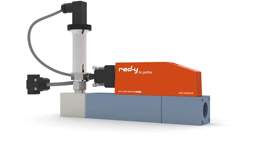
red-y smart pressure controller GSP

Digital Pressure Controller with integrated Flow Measurement
Flow up to 60 ln/min
Aluminium version
Body size ¼”

Elektronische Druckregler für Gase mit integrierter Durchflussmessung

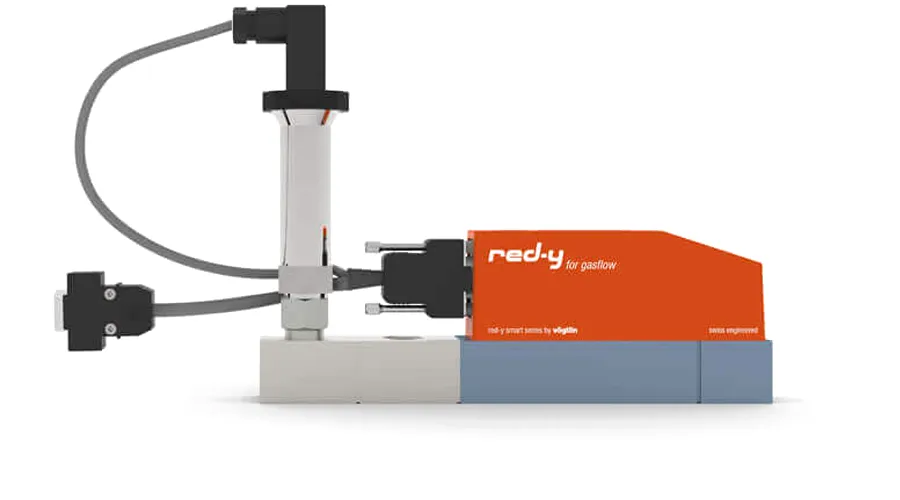
red-y smart controller GSB

Digital Back Pressure Controller with integrated Flow Measurement
Flow up to 60 ln/min
Aluminium version
Body size ¼”

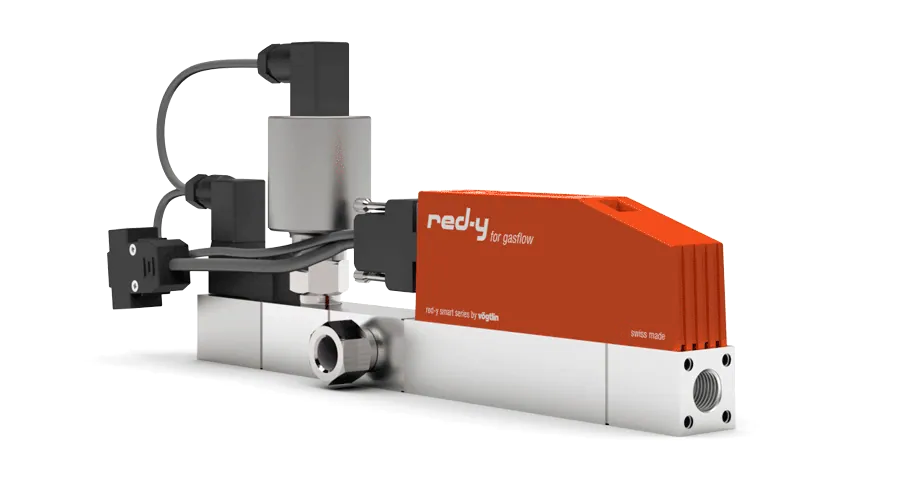
Elektronischer Vordruckregler für Gase mit integrierter Durchflussmessung red-y smart pressure controller GSB 1/2 Zoll

Flow up to 450 ln/min

Pressure controller and back pressure controller with measuring ranges up to 450 ln/min
Gas connection G½”

Vögtlin erarbeitet anspruchsvolle Lösungen für Ihre Durchflussanwendungen

Customized OEM Solutions

Optimize and simplify your processes with our customized & modular flow solutions.

For a wide range of applications the thermal mass flow meters and mass flow controllers offer you a significant optimization and simplification of your processes.

» Contact a Mass Flow Expert
» Read our Application Stories

Tech Specs

Measuring & control ranges Pressure
Pressure control Absolute, differential or gauge pressure
Standard measuring ranges from 30 mbar up to 10 bar (graded)
Turndown ratio: 1 : 100
Back pressure control Absolute, differential or gauge pressure
Standard measuring ranges from 30 mbar up to 10 bar (graded)
Dynamic range depending on the application
Measuring ranges flow
Air/Full scale freely selectable Body size ¼” from 0 … 25 mln/min to 0 … 60 ln/min
Body size ½” from 0 … 60 ln/min to 0 … 450 ln/min
Turndown ratio & accuracy Flow
“Standard” Accuracy: ± 1.0% of full scale*
Turndown ratio: 1 : 50
“Hi-Performance”
(up to 150 ln/min)
Accuracy: ± 0.3% of full scale + ± 0.5% of reading*
Turndown ratio: 1 : 100
Pressure controller with external transmitter, special measuring ranges (e.g. 0-20 Pa) & customer-specific solutions on request
Performance Data
Media (real gas calibration) Air*, O2*, N2, He, Ar, CO2, H2, CH4, C3H8 (other gases and gas mixtures on request)
*O2 & N2 are calibrated with air
Response time Flow Measurement ± 80ms
depending on device configuration & according to SEMI standard E17-1011, 5-100% of range under optimized conditions
Response time Pressure Measurement 150ms
Response time Pressure Control Depending on the measuring section
Repeatability ± 0.2% of full scale (according to SEMI standard E56-0309)
Longterm stability < 1% of measured value / year
Power supply 24 Vdc (18 – 30 Vdc), 15 Vdc on request
Current consumption Standard Meter: max. 100 mA; Controller: max. 250 mA
(with valve type 8 max. 490mA)
Current consumption
Profinet RT / EtherCAT
Meter: max. 125 mA; Controller: max. 340 mA
(with valve type 8 max. 560mA)
Temperature (environment/gas) 0 – 50°C
Body Materials Anodized aluminium,
optional stainless steel electropolished 1.4305 or 1.4404
Seals FKM, EPDM, optional FFKM
Pressure Vacuum up to 10 bar g
Pressure sensitivity <0.2% / bar of reading (typical N2)
Temperature sensitivity 0.025% FS measuring range type / °C
Warm-up time <1 sec. for full accuracy
Integration
Output signals digital RS-485; Modbus RTU (Slave); Lab View-VIs available
Option: ProfiBus DP-V0, DP-V1 / Profinet RT / EtherCAT
Output signals analog 0..20 mA, 4..20 mA, 0..5 V, 1..5 V, 0..10 V, 2..10 V
Analog setpoints Realizable with AD-converter (on request)
Process connection G¼” (BSPP* female) up to 60 ln/min,
G½” (BSPP* female) up to 450 ln/min
*British Standard Pipe Parallel
Inlet section None required
Electrical connection Sub D plug, 9 pole
Mounting orientation Any position (consult manufacturer above 5 bar or vertical mounting)
Safety
Test pressure 16 bara
Leak rate < 1 x 10⁻⁶ mbar l/s He
Ingress protection class IP50 or IP67
EMC EN 61326-1

Accessories

Connection cables, power supplies

wide range of cables and power supply units for fast integration of the red-y smart pressure controllers is available:

  • Cables for communication with PC (USB)
  • Cables for analog communication
  • Power supply (24 Vdc)
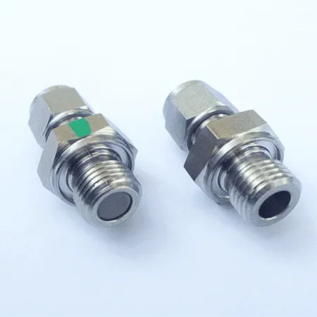
voegtlin massflow fittings compression with filter

Compression fittings with 50μ filter/ Stainless steel 1.4404 / 316L

Type/Connection Seals in FKM Seals in EPDM
G1/4″ to 6mm Part-N° 328-1011 Part-N° 328-1031
G1/4″ to 1/4″ Part-N° 328-1012 Part-N° 328-1032
G1/4″ to 12mm Part-N° 328-1013 Part-N° 328-1033
G1/4″ to 1/2″ Part-N° 328-1014 Part-N° 328-1034
G1/2″ to 12mm Part-N° 328-1006 Part-N° 328-1026
G1/2″ to 1/2″ Part-N° 328-1007 Part-N° 328-1027
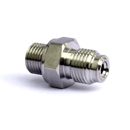
voegtlin massflow fittings vcr

Vacuum fitting (identical to VCR®)

Type/Connection Seals in FKM
G1/4″ / 1/4″ VCR Part-N° 328-1190
G1/2″ / 1/2″ VCR Part-N° 328-1191

VCO® & VCR® are registered Trademarks of Swagelok

Vakuum-Verschraubung angeflanscht

Vacuum fitting flange-mounted (identical to VCR®)

Type/Connection Seals in FKM Seals in EPDM
G1/4″ / 1/4″ VCR Part-N° 328-1192 Part-N° 328-1193

VCO® & VCR® are registered Trademarks of Swagelok

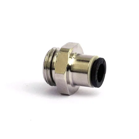
voegtlin massflow fittings legris

Male stud fittings Legris / Brass

Type/Connection Seals in NBR
G1/4″ to 6mm Part-N° 328-1211
G1/4″ to 8mm Part-N° 328-1212
G1/4″ to 10mm Part-N° 328-1213
G1/2″ to 8mm Part-N° 328-1216
G1/2″ to 12mm Part-N° 328-1214
G1/2″ to 14mm Part-N° 328-1215

Downloads

329-2014_de_cablesmart.pdfred-y smart series Cable AccessoriesAccessories DatasheetsEN, DE, FREN, DE, FR
329-2058_de_infosmartpressure.pdfred-y smart pressure controller Product InformationProduct DatasheetsEN, DEEN, DE
329-2071_de_getredy5.pdfSoftware get red-y Product InformationProduct DatasheetsEN, DEEN, DE
329-2079_de_smartdisplay.pdfred-y smart series Display OptionProduct DatasheetsEN, DEEN, DE
329-2132_de_gzbsystems.pdfred-y smart series Gas Block SystemsAccessories DatasheetsEN, DEEN, DE
329-2135_de-triclamp.pdfTri-Clamp FittingsAccessories DatasheetsEN, DEEN, DE
329-3017_ml_getredy.zipSoftware get red-y V5.7.1.3SoftwareMLML
329-3027_de_manualsmart110.pdfred-y smart series Operating Instructions SN>110000Operating InstructionsEN, DEEN, DE
329-3041_de_manualsmart_digicom.pdfred-y smart series Operating Instructions digital CommunicationOperating InstructionsEN, DEEN, DE
399-3030_ml-smart-conformity-ce.pdfred-y smart series Declaration of Conformity CECertificates/StatementsEN, DEEN, DE
399-3031_ml-smart-conformity-ukca.pdfred-y smart series Declaration of Conformity UKCACertificates/StatementsEN, DEEN, DE
811-1221_ml_smart_QSG.pdfred-y smart series Quick Start GuideOperating InstructionsEN, DEEN, DE
LabVIEW_2010.zipLabVIEW VIs (LabVIEW 2010 and higher)SoftwareMLML
LabVIEW_2011.zipLabVIEW VIs (LabVIEW 2011 and higher) SoftwareMLML
LabVIEW_6.zipLabVIEW VIs (LabVIEW 6 and higher)SoftwareMLML
LabVIEW_8_6.zipLabVIEW VIs (LabVIEW 8.6 and higher)SoftwareMLML
vog-ethercat-manual-en.pdfred-y smart & industrial series Operating Instructions EtherCATOperating InstructionsEN
vog-ethercat-twincat-tutorial.zipred-y smart & industrial series Tutorial EtherCAT TwinCatOperating InstructionsEN
vog-profinet-manual-en.pdfred-y smart & industrial series Operating Instructions ProfinetOperating InstructionsEN
vog-profinet-twincat-tutorial.zipred-y smart & industrial series Tutorial Profinet TwinCatOperating InstructionsEN

Tutorials & FAQs

What is the impact of a different reference temperature?

The reference pressure in all units is designed for 1013.25 mbar. If you want to calculate the difference between 0 °C and 20 °C, e.g., the formula is as follows:

(flow at 0°C /273.15)*293.15

(Law of Boyle/Gay-Lussac)

Example: 100 ln/273.15*293.15 = 107,32 ls (=7.3%) This corresponds to a correction of 0.366 % per degree Celsius

How significant is the impact if the operating conditions change (pressure and temperature)?

The thermal mass flow meters and controllers directly measure the number of gas molecules (=mass), which flows past the sensor. The thermal flow measurement principle is therefore insensitive to changes in pressure and temperature. Vögtlin calibrates each unit on two temperatures and a temperature sensor in the gas stream compensates any minor temperature error due to temperature effects in the electronics. Due to this compensation there are almost no measurable temperature effects in the range of between 0…50 °C.

What reference conditions (pressure and temperature) are the devices specified for?

Unlike liquids, gases can be compressed. The volume changes when the temperature and/or the pressure change. When specifying a gas volume, the reference temperature and the reference pressure must thus also always be specified. The flow unit is than referred to as normalized (f.i. ln/min) or standardized flow (f.i. ls/min)

When we refer to “Normal” flow we in general use:
Temperature Tn = 273,15 K, corresponds to 0 °C
Pressure Pn = 1013,25 mbar abs

When we refer to “Standard” flow we in general use:
Temperature Tn = 293,15 K, corresponds to 20 °C
Pressure Pn = 1013,25 mbar abs
See also: http://en.wikipedia.org/wiki/standard conditions

Please note: Not everyone understands standard conditions in the same way. In the case of reference pressure, everyone agrees, but in the case of reference temperature, there are differences:

  • Gas suppliers in Europe do not use 0 °C, but 15 °C as their “Normal condition”

To avoid misunderstandings, the reference conditions are specified clearly in our correspondence.
On request, we also deliver the devices with another reference temperature.

How can the devices be controlled?

The measuring and regulating parameters of the red-y smart series and red-y industrial series can be read out or controlled in an analog, manual and digital manner.

What is required to let the devices communicate to a PC?

Vögtlin offers a wide range of accessories, so that the devices can be operated directly via a PC with very little effort. In detail:

» Cable accessories for the red-y smart series

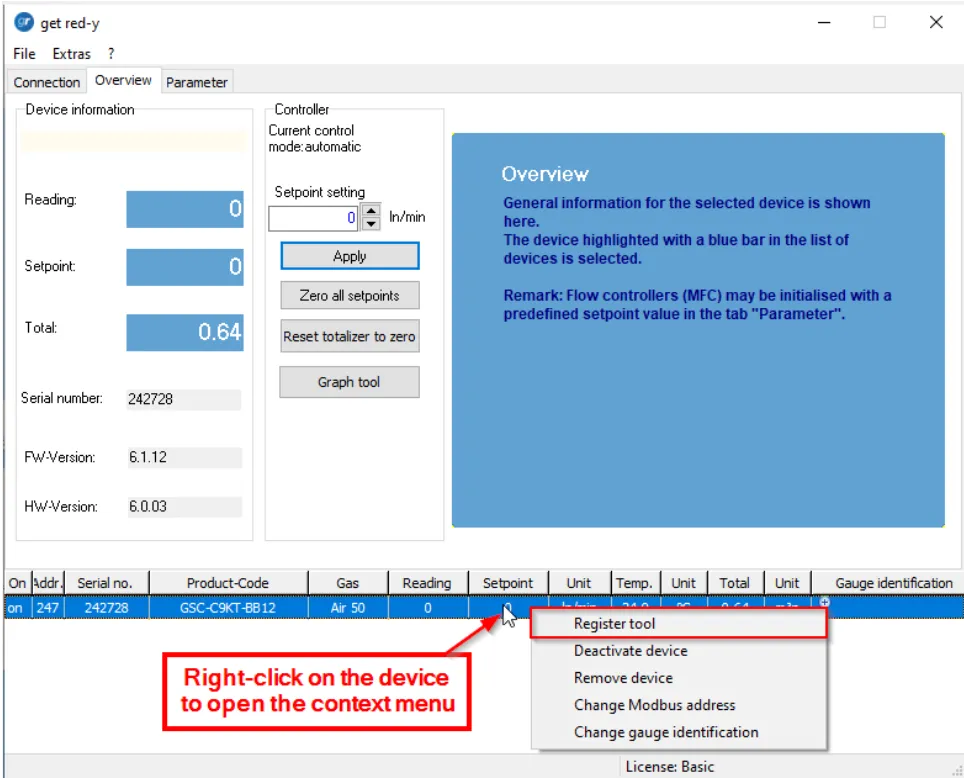
The free software get red-y offers a wide range of possibilities in context with the digital communication:

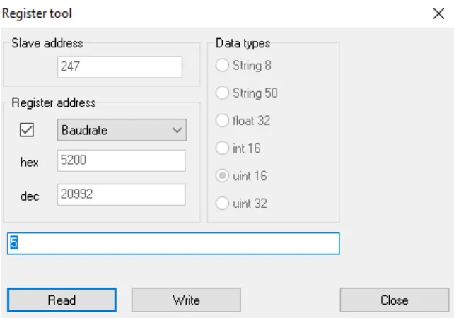
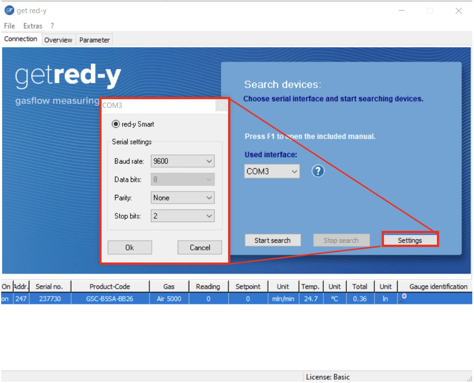
  • Configuration of the serial computer interface
  • Setting the program language
  • Scanning and depicting the bus structure
  • Integrating individual devices into the bus structure
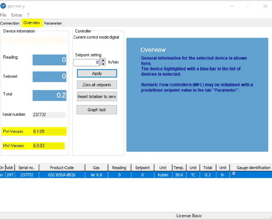
  • Reading the device-specific hardware and software versions
  • Displaying the measuring value, the totalizer and the temperature of a device
  • Setting the set values
  • Resetting totalizer
  • Selecting or changing the regulating parameter sets
  • Setting the PI control parameters and checking performance
  • Selecting the corresponding calibration data set (multi-calibration)

In addition, the following functions can optionally be unlocked:

  • Data logger
  • Mixer

Measuring range too large/small: Can the full scale of the device be adapted on site?

The mass flow meters and controllers of the red-y smart series and red-y industrial series have a very large dynamic range and can be converted to a certain extent on site.

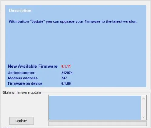
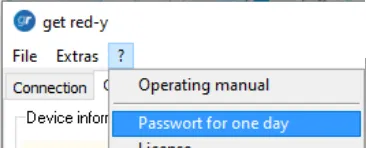
A measuring device can be reprogrammed with the help of our service department by means of the get-red-y software. You will receive a password (valid for one day) for enabling this advanced function. Please contact our service department for more information.

Can the devices also be used in low pressure?

On principle, it is possible to utilize our thermal mass flow meters and controllers in the low pressure range. The sensor allows for an accurate flow measurement down to 100 mbar abs (we never verified lower pressures).

In the case of the flow regulators, a the low pressure is most of the time downstream of the control valve. The valves are vacuum-tight. The following must nonetheless be taken into consideration:

  • The devices have a larger pressure loss in vacuum operation. The tubing should thus be designed to be as large as possible.
  • In vacuum systems there is a higher risk for the forming of condensation which is a problem for the measurement. (The gas must be clean and dry)

What information are required for selecting & sizing the mass flow meters & controllers?

Always provide a description of your application, why and how you want to use the units in your process.
At the very minimum we need the following information:

  • Gas (Specify all components if it is a gas mixture with their %)
  • Maximum and minimum flow and they units (f.i. ln/min or Gr/hr)
  • Pressure at the installation point (Inlet of the flow meter)
  • In case of a Mass flow controller the pressure behind the Mass flow controller (Your process pressure)
  • Minimum and maximum gas and ambient temperature
  • How is the device to be read out/controlled: visually on site / by means of analog signal (please define, e.g. 4-20 mA) / digitally via standard software get-red-y / SPS / client’s own system
  • Position (vertical/Horizontal) and any specific mounting and location information (f.i. required IP rating or Ex certification)

Does the mounting position need to be considered?

Basically, the red-y for gasflow mass flow meters and mass flow controllers can be installed in any position. At higher pressures and with dense gases such as krypton, a slight zero-point drift may occur. We therefore recommend using the devices horizontally wherever possible.
For the red-y smart pressure controllers with a small measuring range, the mounting position must be known. The dead weight of the pressure measuring cell can cause a zero point drift.

Does a massflow unit need a warm up time?

No, all  red-y for gasflow devices are ready for immediate operation.

What is the impact of the moisture of the gas?

Moist gas of up to approx. 80 % rh has only a slight impact on the measuring accuracy. However, make sure that no condensation can take place in the measuring device. The condensation could settle on the sensor which could lead to inaccurate measurements. In the event that a measuring device has come into contact with condensation, it can for the most part be rinsed with a dry gas, such as N2. See also the remarks in the operating instructions.

What device parameters can be changed on site?

The device parameters will be configured in the factory prior to delivery according to the data provided by you.
The following parameters can be set changed with the help of the get-red-y software:

  • Selecting the regulating parameter sets slow/medium/fast
  • Establishing your own control parameters (PID)
  • Converting the flow unit
  • Converting to a different reference temperature
  • Setting a start-up set value and/or a set value delay (soft start)
  • In the case of the option of a configured display: setting the displayed measured variables
  • For service purposes, additional parameters can be accessed by means of a (temporally) password

Do I have to place a filter in the gas line to the flow meter/controller?

If you use gas from a bottle which is clean and dry, there is, in general no need for a filter.

However, there is a risk during start-up of the devices, because dirt particles could be present in the line. It is recommended to install a bypass system, so that the line can be rinsed or can be exposed in response to possible repairs.

In the event that ambient or compressed air is used, the installation of a moisture and dust filter is strongly recommended.

Troubleshooting: Is there a checklist?

Within the troubleshooting pages in the operating instructions, we have summarised error patterns, possible causes and possible measures. If you do not recognise your error pattern or the suggested action is unsuccessful, please contact your Sales Ppartner. If you return the appliance, please refer to the ‘Returns’ section in the operating instructions.

How can the devices be cleaned?

Depending on the type of contamination, the devices can be cleaned on site. You can find more information on this topic in the operating instructions.

Is there a possibility for a remote maintenance in the event of malfunction?

Yes. In some cases it is convenient when we can access the client’s PC directly and solve issues online. Please contact us!
You can download the free software TeamViewer for remote support here.

Periodic calibration: How often do the devices need to be calibrated?

In principle, the user himself determines the calibrating interval. People often use one per year or in case of very clean gas, one per 2 years. The following questions/points can be helpful:

  • How important is it to maintain the accuracy of the measuring device?
  • What is the maximum allowable deviation?
  • Can the user determine the deviation of the measuring devices himself by means of a reference?
    Prior to installation into the system, the actual state is detected by means of a reference device. The customer determines the periodic inspection himself. It is important to make sure thereby that the measuring setup is always the same.
  • Internal or external specifications determine the interval:
    Is a periodic calibration from an accredited body required (e.g. Dakks (previously DKD) or SCS)?
  • Is the actual state determined prior to a recalibration?
    Yes, provided that the measuring device works, the current deviation is determined. A report is generated thereby. If it lies outside of the device specification, the measuring device is readjusted (adapted to a reference).

We suggest the following calibration interval:

1. First inspection after one year
2. After several calibrations have been made in succession, the deviation of calibration to calibration must be evaluated. Based on these data, a decision can be made to adapt the calibrating intervals.

The following influences can lead to an increased deviation:

1. No stable flow, caused by pulsating pumps, e.g.
2. The gas condenses or carries along liquid or dusty particles (applications with ambient air are particularly susceptible to contaminations. A filter needs to be provided here).
3. The effective pressure deviates considerably from the calibrated pressure (+/- 0,2%/bar).
4. The gas/gas mixture is not consistent with the calibrated gas.
5. The aging of electronic components can cause changes, sometimes even improvements. Electrical changes appear as a result of aging or gradual burning of components, which impact the quality of the output signal.