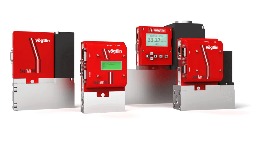
SmartTrak® series

Premium Capillary Mass Flow Meters and Mass Flow Controllers for Gases

The SmartTrak® thermal mass flow meters and mass flow controllers are true multi-gas digital MFC designed to deliver smooth, stable, accurate, and repeatable gas mass flow control you can rely on, every time.

Note: SmartTrak® series units are available in Europe only!

Key Features

SmartTrak® Capillary Mass Flow Meters & Controllers for Gas
  • Gas Mass flow meter and controller based on capillary technology with up to 0.5% full scale accuracy
  • All wetted parts stainless steel, 0.8 Ra µm electro polished surfaces. Cleanroom assembly possible
  • Ranges from 0-10 mln/min to 0-500 ln/min
  • Every units has 10 pre-programmed gases, customer selectable
  • Choice of customer selectable engineering units, gases, outputs, range, etc.
  • Due to the advanced engineering, accuracy for every gas selected
  • Operating pressure standard 35 barg
  • Suitable for most corrosive and aggressive dry and clean gases
  • Optional local display and local setpoint/configuration
  • Most analogue and RS232 communication standard on each unit
  • Active temperature compensation for temperature independent operation
  • Strong direct driven valve
  • Optional Modbus communication
  • Modbus module with analogue input/outputs and I/O alarm contacts
  • Wide choice of elastomers and valve seal materials
  • Long term stability sensor
  • Free configuration software for MS Windows
  • Very low pressure differentials possible due to big valve
  • Every unit calibrated with Primary NIST traceable high accuracy reference standard

Versions

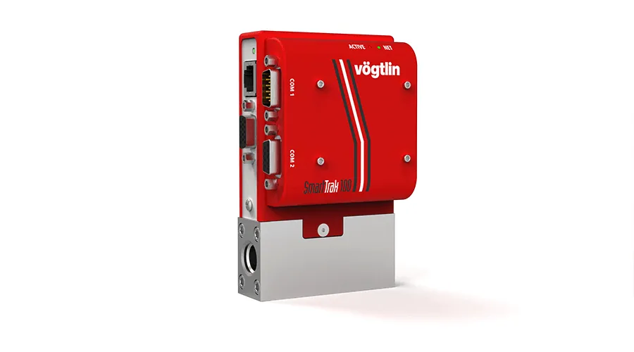
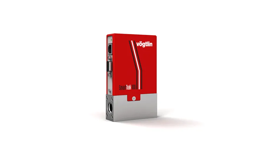
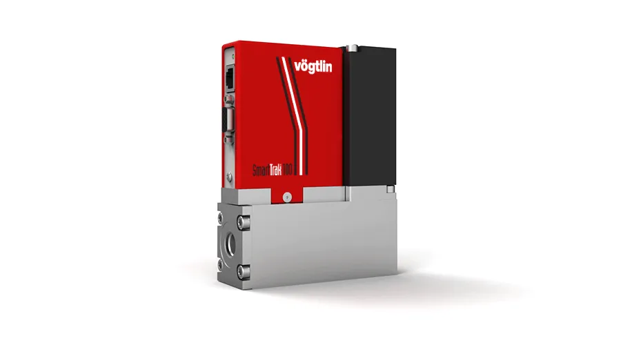
SmartTrak®100 Capillary Gas Flow Meter with RS232 Interface

SmartTrak® 100L (Low Flow)

Capillary Mass Flow Meters and Mass Flow Controllers
Flows from 0-10 mln/min to 0-50 ln/min
Pressure up to 34.5 barg

SmartTrak®100 Medium Flow Capillary Gas Flow Meter and Controller

SmartTrak® 100M (Medium Flow)

Capillary Mass Flow Meters and Mass Flow Controllers
Flows from 0-20 to 0-200 ln/min
Pressure up to 34.5 barg

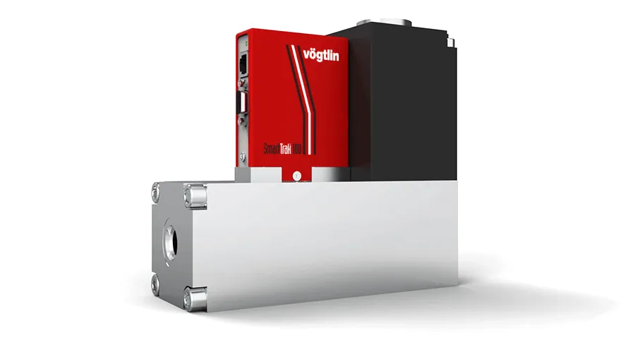
SmartTrak®100 High Flow Capillary Gas Flow Meter and Controller

SmartTrak® 100H (High Flow)

Capillary Mass Flow Meters and Mass Flow Controllers
Flows from 0-500 ln/min
Pressure up to 34.5 barg

Interfaces

SmartTrak®100 Capillary Gas Flow Meter with RS232 Interface

SmartTrak@ series

Standard version with analog signals and digital RS232 interface

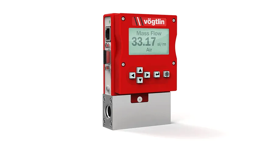
SmartTrak®100 Capillary Gas Flow Meter with local display (Pilot Module)

SmartTrak@ series / Pilot Module

Optional version with local display interface (Pilot Module)

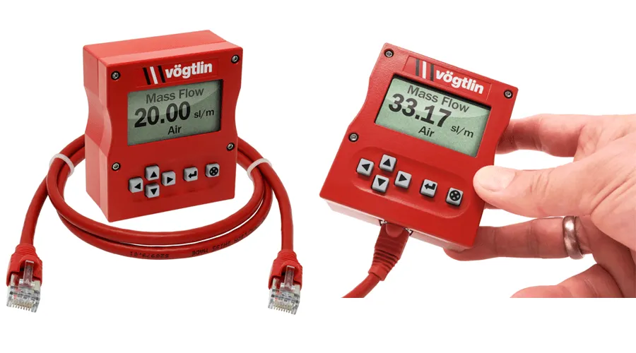
SmartTrak®100 Capillary Gas Flow Meter with remote display (Remote Pilot Module)

SmartTrak@ series / Pilot Remote Module

Optional version with remote display interface (Remote Pilot Module)

SmartTrak®100 Capillary Gas Flow Meter with RS485 Interface

SmartTrak@ series with Modbus RTU

Optional version with Modbus RTU interface (RS485)

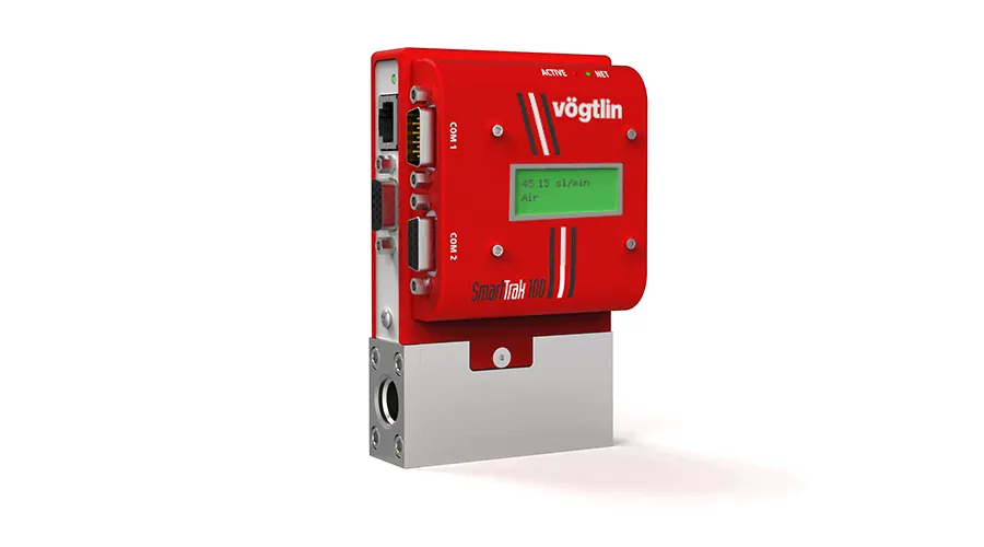
SmartTrak®100 Capillary Gas Flow Meter with RS485 Interface and Display

SmartTrak@ series with Modbus/Display

Optional version with Modbus RTU interface (RS485) and local display

Tech Specs

Measuring ranges
Air/Full scale freely selectable SmartTrak® 100L (Low Flow): 0-10 mln/min to 0-50 ln/min
SmartTrak® 100M (Medium Flow): 0-20 to 0-200 ln/min
SmartTrak® 100H (High Flow): 0-100 to 0-500 ln/min
Flow ranges specified are for an equivalent flow of nitrogen at 1013.25 mbara
(760 mm Hg) and 0°C (32°F)
For other gases and reference conditions please contact the factory.
Instrument versions
“Standard”
The economic solution
Accuracy: ± 1.0% of full scale*
Turndown ratio: 1 : 50 (Controller), 1 : 100 (Meter)
“Hi-Performance”
With high accuracy
Accuracy: ± 0.5% of full scale*
Including 10 point certificate
Hi-performance is only possible for:
Flow range: up to 50 slpm or nlpm (valid from 10 to 100% of the calibrated range)
Gases: Air, Nitrogen, Helium or Argon
Other gases and flow: Contact the factory
Only valid for units up to an operating pressure of 10 barg and over the temperature range
10°C to 30°C in a horizontal position.
The accuracy is only guaranteed under calibrated conditions and is only valid for a period of 6 months after the date of calibration.
Valid for 10 to 100% of FS.


*An additional error of ±0.25% may apply for analogue signals
Performance Data
Media (real gas calibration) All gases and gas mixtures that are compatible with the selected material.
There might be limitations to some corrosive gases
Response time 2 seconds (typical) to within ± 2% of final value (includes settling time),
faster or slower available upon request (controllers only)
Repeatability ± 0.2% of full scale (according to SEMI standard E56-0309)
Longterm stability Typical < 2% of measured value / year
Power supply Mass Flow Meters:
15-24 VDC ±10%, (230 mA, regulated)
Mass Flow Controllers:
C100L: 24 VDC ±10% (500 mA, regulated)
C100M: 24 VDC ±10%, (800 mA, regulated)
C100H: 24 VDC ±10%, (1260 mA, regulated)
(ripple should not exceed 100 mV peak-to-peak)
Operation pressure 0-35 barg (0 – 500 psig)
Temperature (environment/gas) 0 – 50°C (32 – 122°F)
Pressure sensitivity <0.15% / bar (<0.01% / psi) FS (typical N2, horizontal mount)
Temperature sensitivity <0.05% FS measuring range type per 1°C (<0.025% per 1°F)
Warm-up time < 15 min for full accuracy
Materials
Meter all wetted metal parts 316SS (1.4404)
Controller body/sensor materials 316SS (1.4404)
Controllers valve post materials C100L/C101: 316SS/410SS/430SS (1.4404/1.4006/1.4016)
C100M: 416SS/430SS (1.4005/1.4016)
C100H: 316SS/416SS/430SS (1.4404/1.4005/1.4016)
Electronic Housing Powder coated steel
Seals FKM (Viton®) Options: Neoprene
Valve seals FKM (Viton®) Options: Neoprene, Kalrex®
Integration & Installation
Output signals analog Linear 4–20 mA or 0-20 mA, 500 ohms maximum loop resistance
and one of the following (user selectable):
Linear 0–5 VDC, 1000 ohms minimum load resistance
Linear 0-10 VDC, 1000 ohms minimum load resistance
Linear 1-5 VDC, 1000 ohms minimum load resistance
Setpoint signals analog Analog (choice of one, user selectable):
Linear 4–20 mA, 0-20 mA. 0–5 VDC, 0-10 VDC, 1-5 VDC
Output signals digital RS232 Optional: RS485; Modbus RTU (Slave)
Process connection Fittings included. Options: Swagelok® (Compression), VCR, VCO, NPT
Inlet section None required
Electrical connection D-15 High density plug (15 pins) female
Mounting orientation All orientations are possible but must be defined at time of order
Safety
Burst pressure 52 bar (240 psi)
Leak rate < 1 x 10⁻⁹ mbar l/s He
Ingress protection class IP20 
EMC EN 61326-1
ATEX Certification None

Firmware

SmartTrak® series Configuration Software

Communication with the SmartTrak® series over RS232
Recommended cables: 100-CRN + Optional 100-SerialUSB

SmartTrak® series COMPOD Configuration Terminal Software

To set the communication settings in a COMPOD a terminal software is required.
The free software PuTTY or Windows HyperTerminal can be used.
For further instructions see chapter 7 on the COMPOD operating instructions.
Recommended cables: 100-CRC and RS485 to USB converter

SmartTrak® series DLL Files

The SmartTrak® DLL helps the customer to create their own software, exactly according to their specifications.
The DLL handles all communication, synchronization and guards line stability.

For Labview drivers please contact the factory.

Downloads

vog-smarttrak100-datasheet-de.pdfSmartTrak® 100 Product InformationProduct DatasheetsEN, DEEN, DE
811-1224_ml_smarttrak100_QSG.pdfSmartTrak® series Quick Start GuideOperating InstructionsEN, DEEN, DE
vog-smarttrak-manual-de.pdfSmartTrak® series Operating instructionsOperating InstructionsEN, DEEN, DE
vog-smarttrak-configuration-software.zipSmartTrak® series Configuration SoftwareSoftwareEN
vog-smarttrak-dll-files.zipSmartTrak® series DLL FilesSoftwareMLML
vog-smarttrak-compod-de.pdfSmartTrak® series COMPOD Interface DatasheetProduct DatasheetsEN, DEEN, DE
vog-smarttrak-power-supply-configurations-de.pdfSmartTrak® 100 Power Supply & Cabling OptionsAccessories DatasheetsEN, DEEN, DE
vog-smarttrak-manual-compod-de.pdfSmartTrak® series COMPOD Operating instructionsOperating InstructionsEN, DEEN, DE
vog-ads-smarttrak-100-series.xlsApplication Data Sheet SmartTrak® series 100 / 101Inquiry FormsMLML
vog-ads-smarttrak-compod-module-ads.xlsApplication Data Sheet SmartTrak® series Compod ModuleInquiry FormsMLML
399-3038_ml-smarttrak-conformity-ce.pdfSmartTrak® series Declaration of Conformity CECertificates/StatementsEN, DEEN, DE
399-3039_ml-smarttrak-conformity-ukca.pdfSmartTrak® series Declaration of Conformity UKCACertificates/StatementsEN, DEEN, DE
vog-smarttrak-corrosive-gas-policy.pdfSmartTrak® series Corrosive Gas PolicyCertificates/StatementsMLML

Tutorials & FAQs

Do I have to place a filter in the gas line to the flow meter/controller?

If you use gas from a bottle which is clean and dry, there is, in general no need for a filter.

However, there is a risk during start-up of the devices, because dirt particles could be present in the line. It is recommended to install a bypass system, so that the line can be rinsed or can be exposed in response to possible repairs.

In the event that ambient or compressed air is used, the installation of a moisture and dust filter is strongly recommended.

Troubleshooting: Is there a checklist?

Within the troubleshooting pages in the operating instructions, we have summarised error patterns, possible causes and possible measures. If you do not recognise your error pattern or the suggested action is unsuccessful, please contact your Sales Ppartner. If you return the appliance, please refer to the ‘Returns’ section in the operating instructions.

How can the devices be cleaned?

Depending on the type of contamination, the devices can be cleaned on site. You can find more information on this topic in the operating instructions.

Periodic calibration: How often do the devices need to be calibrated?

In principle, the user himself determines the calibrating interval. People often use one per year or in case of very clean gas, one per 2 years. The following questions/points can be helpful:

  • How important is it to maintain the accuracy of the measuring device?
  • What is the maximum allowable deviation?
  • Can the user determine the deviation of the measuring devices himself by means of a reference?
    Prior to installation into the system, the actual state is detected by means of a reference device. The customer determines the periodic inspection himself. It is important to make sure thereby that the measuring setup is always the same.
  • Internal or external specifications determine the interval:
    Is a periodic calibration from an accredited body required (e.g. Dakks (previously DKD) or SCS)?
  • Is the actual state determined prior to a recalibration?
    Yes, provided that the measuring device works, the current deviation is determined. A report is generated thereby. If it lies outside of the device specification, the measuring device is readjusted (adapted to a reference).

We suggest the following calibration interval:

1. First inspection after one year
2. After several calibrations have been made in succession, the deviation of calibration to calibration must be evaluated. Based on these data, a decision can be made to adapt the calibrating intervals.

The following influences can lead to an increased deviation:

1. No stable flow, caused by pulsating pumps, e.g.
2. The gas condenses or carries along liquid or dusty particles (applications with ambient air are particularly susceptible to contaminations. A filter needs to be provided here).
3. The effective pressure deviates considerably from the calibrated pressure (+/- 0,2%/bar).
4. The gas/gas mixture is not consistent with the calibrated gas.
5. The aging of electronic components can cause changes, sometimes even improvements. Electrical changes appear as a result of aging or gradual burning of components, which impact the quality of the output signal.