Q-Flow

Variable Area Flowmeters for Gases with attractive Design

Our proven Q-Flow is a modern VA-flowmeter for gases built on the variable area principle. Designed in close collaboration with users, it combines our long experience and practical shop-floor requirements.

Key Features

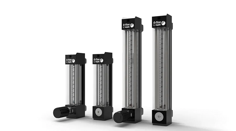
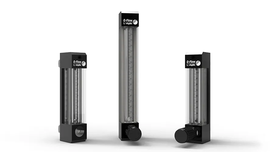
Variable Area Flowmeters Q-Flow with 2 measuring tube sizes

Glass Measuring Tubes in 2 Sizes

The flowmeters are available with glass tube lengths of 80mm and 140mm.

Measuring ranges from 0.06 ln/min up to 50 ln/min for Air @ 1013 mbar abs / 20°C
Maximum pressure: 10 bar / Maximum temperature: 100°C

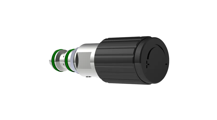
Tightly Closing Precision Control Valves

The devices are equipped with precise, hysteresis-free 15-way control valves. See Needle Valves M-Flow for more information.

Various rotary knobs are available on request.

Massemesser für Gase mit
Intelligent Instrument Design

The compact and attractive design enables quick replacement of components

Standard Scale for Air

The measuring glass is supplied with a standard scale for air (operating conditions 20°C / 1013mbar abs). Conversion factors for other gases and other operating conditions are available.

mm-scale with flow rate table and direct reading scales for other gases and pressures on request.

Aluminium Body

The bodies are available in aluminium. Sealing material FKM.

Body in stainless steel 1.4305 and sealing materials EPDM or FFKM on request.

Customized Versions

We also offer custom designed products. Get in touch with us for further information!

Versions

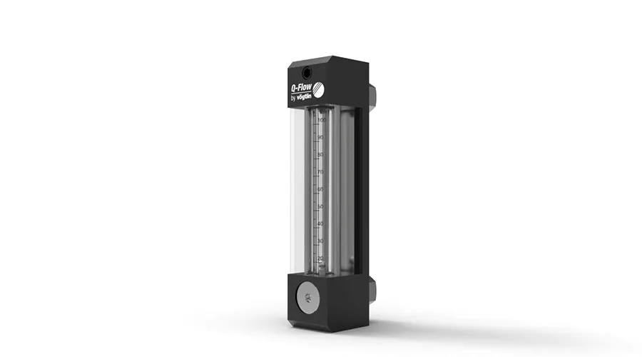
Variable Area Flowmeters (VA-Flowmeters) for Gases Q-Flow without valve

Q-Flow Variable Area Flowmeter

Aluminium version without valve

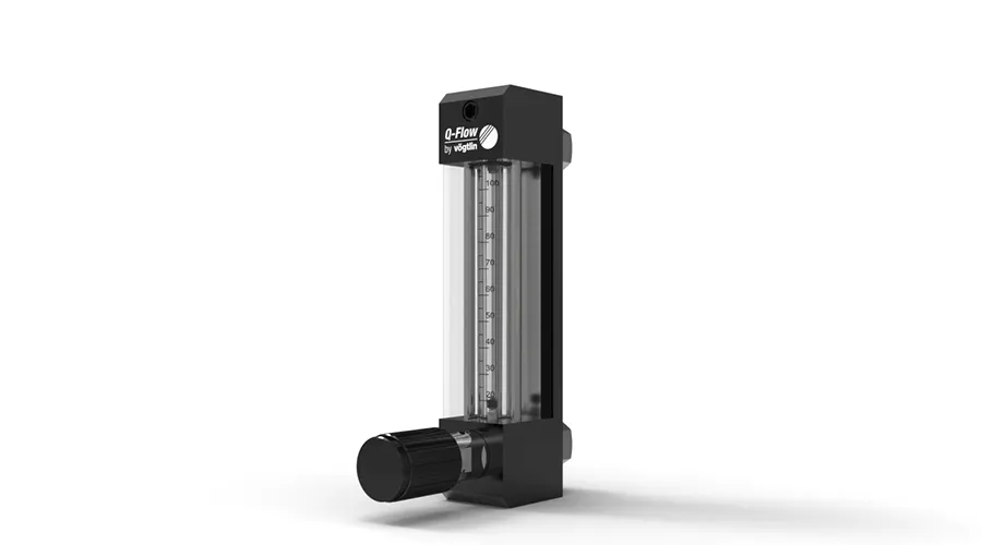
Variable Area Flowmeters (VA-Flowmeters) for Gases Q-Flow with valve

Q-Flow Variable Area Flowmeter

Aluminium version
Valve at the Inlet

Variable Area Flowmeters Q-Flow with 2 measuring tube sizes

Q-Flow Variable Area Flowmeter

The flowmeters are available in two sizes with valve at the inlet and without valve.
Body in stainless steel 1.4305, sealing materials EPDM and FFKM and valve at the outlet on request.

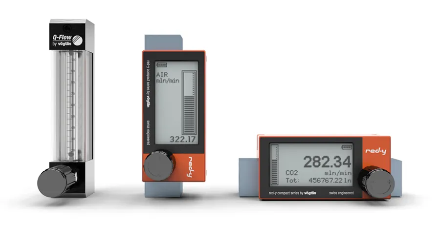
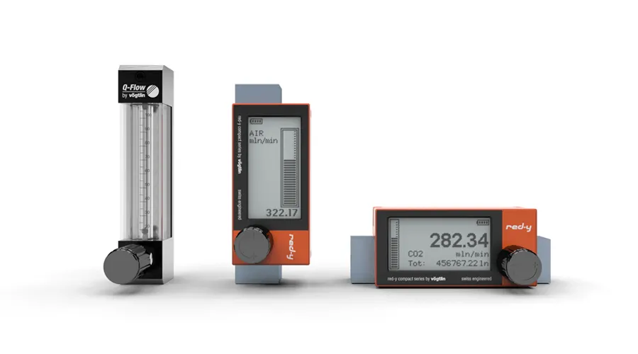
The battery powered digital mass flow meter red-y compact series are a unique va-meter alternative

Looking for a Digital Alternative?

Battery Powered Digital Mass Flow Meters with Needle Valve

  • AA battery powered device with touch display
  • MEMS sensor technology
  • High accuracy & dynamics
  • Wide choice of flow units
  • Use as a meter, regulator or switch
  • Measuring ranges from 25 mln/min up to 450 ln/min
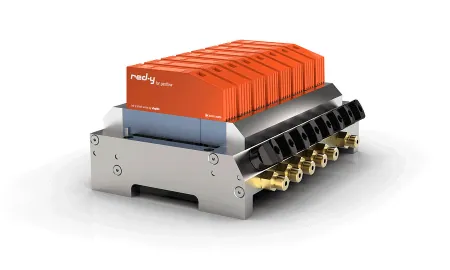
red y smart thermal mass flow controller gsc oem setup 450x270 1

Customized OEM Solutions

Optimize and simplify your processes with our customized & modular flow solutions
For a wide range of applications the thermal mass flow meters and mass flow controllers offer you a significant optimization and simplification of your processes.

» Contact a Mass Flow Expert
» Read our Application Stories

Downloads

139-2011_de_infoQ-flow.pdfQ-Flow Product InformationProduct DatasheetsEN, DEEN, DE
139-3005_de_manualqflow.pdfQ-Flow Operating InstructionsOperating InstructionsEN, DEEN, DE
811-1234_ml_flowline-QSG.pdfFlowline (Q-Flow/M-Flow) Quick Start GuideOperating Instructions

Tutorials & FAQs

Do I have to place a filter in the gas line to the flow meter/controller?

If you use gas from a bottle which is clean and dry, there is, in general no need for a filter.

However, there is a risk during start-up of the devices, because dirt particles could be present in the line. It is recommended to install a bypass system, so that the line can be rinsed or can be exposed in response to possible repairs.

In the event that ambient or compressed air is used, the installation of a moisture and dust filter is strongly recommended.
How can the devices be cleaned?

Depending on the type of contamination, the devices can be cleaned on site. You can find more information on this topic in the operating instructions.

How does a variable area flow meter work?

A VA-flowmeter consists of a tapered tube, typically made of glass with a ‘float’, actually a shaped weight, inside that is pushed up by the drag force of the flow and pulled down by gravity. Drag force for a given fluid and float cross section is a function of flow speed squared only.

A higher volumetric flow rate through a given area increases flow speed and drag force, so the float will be pushed upwards. However, as the inside of the VA-flowmeter is cone shaped (widens), the area around the float through which the medium flows increases, the flow speed and drag force decrease until there is mechanical equilibrium with the float’s weight.

Floats are made in many different shapes, with spheres and ellipsoids being the most common.

The variable area flow meter for gases is highly dependent on the pressure in the measuring tube. The position of the control valve must be considered thereby (see also valve at the inlet or outlet).

What conditions (pressure and temperature) are the devices designed for?

Gases can be compressed. Consequently, pressure and temperature (and the kind of gas) have a direct impact on the display of the flow meter. We therefore calibrate the unit for the specific customer conditions that have been provided at the time of the order.

The flow values indicated on the flow table or on the measuring tube always refer to the depressurised state at 0°C and 1013.25 mbar abs. A different reference temperature or reference pressure is not possible.

If the temperature and pressure varies a lot we recommend you us a digital red-y compact flowmeter unit which automatically compensates for changes in pressure and temperature.

Valve at the inlet or outlet: What are the bases for the decision?

The following principles apply:

It is significant for the design that conditions, which are as constant as possible, are to be strived for in the measuring tube. The application determines the point of installation of the regulating valve. Most of the processes are close to atmospheric at the outlet side. In this case, the flow control valve is placed on the inlet.

There are processes, in which the pressure is not stable downstream from the flow meter. In this case, the regulating valve needs to be placed at the outlet. Warning: In this configuration, it is very important for the adjusted inlet pressure to be stable and to coincide with the designed pressure in the measuring tube. This arrangement is considerably more stable, because the depressurizing takes place downstream from the regulating valve (see also stable flow in response to changing conditions).

Create a stable flow at fluctuating back pressures

A flow can be stabilized with a simple trick in the event of an unstable back pressure. When using regulating valves, the following principle applies in the case of stable system pressure: The flow remains constant, provided that the downstream pressure does not exceed 50% of the inlet pressure.
This principle can be applied to all regulating valves from our assortment of goods.

What process information is required for the design of the measuring device?

We require the following information in order to provide you with an optimal solution: gas type, desired measuring range, temperature, inlet pressure and outlet pressure. It is wise to submit the range under which these variable change as well.

Where can the measuring value be read on the variable area flow meter?

The center of the sphere, thus where the sphere has the largest horizontal diameter, serves as read-out point.

Which measuring scales are available?

By default, a direct reading standard scale for air is setup according to the data sheet.
If you use the meter for a different gas and/or for different operating conditions, you can use the conversion factors which are listed in the data sheet.

The direct reading scale (also called product scale) is designed for a fixed operating condition.

The millimeter scale is used when the customer wants to use the meter under different operating conditions. For this purpose, appropriate tables are provided.